In 30 Seconds
Adding a seventh joint turns a robot from a positioner into a dexterous manipulator: it can reach around obstacles, dodge singularities, and reposition its elbow while holding the tool perfectly still. But redundancy only pays off if every joint is sized and configured correctly. This guide covers the classic shoulder–roll–shoulder (S-R-S) 7-axis layout, how to map each joint to a robot joint module, and what redundancy costs you in weight, price, and control complexity.
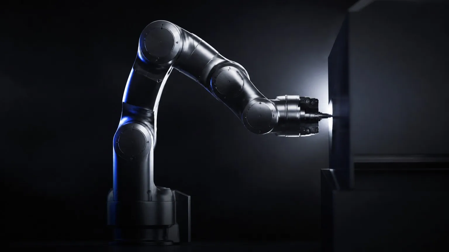
Redundancy lets a 7-axis arm reach around obstacles while keeping the tool pose fixed.
1. Why Redundant Arms?
A 6-axis arm can place its tool in any position and orientation — in theory. In practice, the available joint range shrinks near singularities, where small wrist motions demand enormous joint speeds. A 7th axis adds redundancy, and with it four practical abilities:
- Singularity avoidance — the controller picks an arm configuration that keeps all joints away from degenerate poses.
- Obstacle avoidance — the arm can reach around a fixture with its elbow, not just its wrist.
- Null-space motion — the elbow can move (e.g., tuck in for a tight corridor) while the tool pose stays fixed.
- Torque optimization — the controller can shift load between shoulder and elbow joints in real time, keeping heavy joints inside their continuous-torque envelope.
That last point is the one that matters most to joint sizing: a redundant arm is not just a 6-axis arm with an extra module — it is an arm whose load distribution changes dynamically.
2. The S-R-S Configuration
The dominant 7-axis layout is S-R-S: a 3-axis spherical shoulder (roll–pitch–roll), a single elbow pitch, and a 3-axis spherical wrist. Intersecting axes at the shoulder and wrist keep inverse kinematics tractable and eliminate wrist singularities. Two design consequences follow:
- Intersecting axes need compact joints — the three shoulder axes are packed close together, so short axial height matters as much as torque.
- Hollow-shaft routing must be checked early — cables need a protected path through the selected joints. Confirm the bore, connector and bend-radius requirements from the model datasheet before freezing the arm layout; see our wiring guide for routing details.
3. Sizing the Joints
With redundancy, sizing starts from the tool and works backwards, because wrist mass cascades through the entire arm. A worked example: a 7-DOF arm with 1.35 m reach and 10 kg payload, total arm mass ≈19 kg.
| Joint | Role | Calc. Peak (Nm) | Recommended Module | Headroom |
|---|---|---|---|---|
| J1 (Base roll) | Whole arm + payload | 72 | PP-20 (107 Nm) | 49% |
| J2 (Shoulder pitch) | Gravity load on arm + payload | 64 | PP-20 (107 Nm) | 67% |
| J3 (Shoulder roll) | Dynamic torque redistribution | 48 | PP-17 (70 Nm) | 46% |
| J4 (Elbow pitch) | Distal arm + payload | 28 | PP-14 (36 Nm) | 29% |
| J5 (Wrist pitch) | Tool + small payload | 12 | PP-14 (36 Nm) | 67% |
| J6 (Wrist yaw) | Tool orientation | 8.5 | PP-11 (10.5 Nm) | 19% |
| J7 (Wrist roll) | Tool rotation | 3.9 | PP-08 (4.5 Nm) | 15% |
Three observations on this map:
- The shoulder carries the arm. J1 and J2 together account for more than half of the arm's torque budget (57% in this example). Because null-space control can push load between them, give both at least 25% headroom — a redundant arm that runs at its shoulder limit loses its redundancy advantage.
- Wrist joints need margin too. The current map uses PP-11 and PP-08 only where the calculated torque is below their published ratings; increase the model size when acceleration, payload inertia or contact loads reduce the margin.
- Impact margins matter for the elbow: a 7-DOF arm that operates near obstacles should validate peak torque and collision behavior against the selected model's current datasheet.
4. Control & Communication
Redundancy resolves at the controller, not the hardware — but the hardware has to be worthy of the controller:
- EtherCAT is the right bus: seven joints plus a tool must run in one synchronized cycle, and distributed clocks keep the null-space solver's torque commands phase-aligned. See our EtherCAT setup guide.
- Dual absolute encoders (17-bit, motor-side + output-side) give the controller true output position on every joint — essential when the null-space solver is optimizing elbow motion and needs accurate joint states, not estimates.
- Per-joint torque and velocity limits turn each module into a safety boundary: with collision detection based on current and encoder twist, the arm can stop or yield within a control cycle — the same mechanism covered in our cobot joint guide.
- Brake configuration should be confirmed for the selected model and application. A redundant arm can hang in gravity-defying configurations, so E-stop holding requirements belong in the quotation and safety review.
5. When 6 DOF Is Enough
Redundancy is not free. The 7th joint adds roughly 10–15% to arm cost and mass, plus real controller complexity. Ask whether your task actually needs it:
| Choose 7-DOF when… | Choose 6-DOF when… |
|---|---|
| Reaching inside or around fixtures | Repeatable point-to-point paths in open space |
| Tool orientation must stay fixed while repositioning | Fixed approach angles are acceptable |
| Human-like manipulation or teleoperation | Palletizing, welding paths, machine tending |
| Singularity-free motion is a hard requirement | Trajectories are pre-planned away from singularities |
6. Next Steps
A 7-DOF arm is the fastest-growing category in collaborative and humanoid robotics — and it is built almost entirely from catalog joint modules like the PP-series. The selection framework is the same as any arm: size backwards from the tool, keep 25%+ headroom on the shoulder, and verify hollow-shaft diameters before you commit to a wiring scheme.
Related reading: How to Calculate Torque Requirements for Robot Joints and How to Design a Modular Robot Arm Using Standardized Joint Modules.
Designing a 7-DOF Arm?
Send us your reach, payload, and joint map — we'll validate the sizing, provide CAD models, and quote within 24 hours.
Request Quote & Datasheet