What exactly is inside those compact, metallic cylinders that power the world's most advanced robots? A robot joint module is much more than just a motor; it is a complete servo system engineered for density and precision. By peeling back the housing, we can see how five distinct engineering disciplines—electromagnetic, mechanical, electronic, sensory, and thermal—converge into one unit.
1. The Frameless Motor: High Torque, Zero Waste
At the heart of every PlaPivot module is a frameless, brushless DC (BLDC) motor. Unlike standard off-the-shelf motors, these are designed to be 'poured' directly into the joint housing. They feature a large diameter and many pole pairs, which provides very high 'torque density'—the ability to generate massive rotational force without a huge physical footprint. The hollow-shaft design is a key feature, allowing power cables and communication lines (like EtherCAT) to pass through the center of the joint. This enables the 'infinite rotation' or neat internal wiring seen in modern cobots.
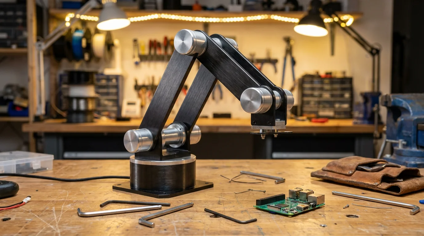
Technical illustration for Inside a Robot Joint Module: Motor, Encoder, Brake & Driver Explained.
2. Harmonic Reducers: The Torque Multiplier
Since BLDC motors naturally want to spin fast (thousands of RPM) but robots need to move slowly and with high force, a gear reducer is required. We use harmonic drive reducers because they offer zero backlash and high reduction ratios (typically 100:1) in a single stage. This means the 0.5Nm produced by the motor becomes 50Nm at the output flange. The 'Flexspline' inside the reducer is made from high-strength alloy steel, capable of millions of cycles of elastic deformation. This component is the most expensive part of the module and determines the overall precision and lifespan of the robot.
3. Dual Absolute Encoders: Knowing Where You Are
A joint module has two sets of 'eyes.' The motor-side encoder (usually 18-bit or 20-bit) tells the driver how to fire the motor coils for smooth rotation. The output-side encoder (up to 23-bit) tells the robot exactly where its arm is in 3D space. Because these are 'absolute' encoders, they use a unique bit pattern for every position, meaning the robot never loses its place, even if the power is cut. It doesn't need to 'home' or move to a limit switch on startup, which is a major safety advantage in collaborative environments where a robot might be sharing space with humans.
Technical illustration for Inside a Robot Joint Module: Motor, Encoder, Brake & Driver Explained.
4. Integrated Driver and Power Electronics
Wrapped around the motor is a circular PCB containing the servo driver. This board takes in 24V-48V DC and high-level commands, then uses high-speed MOSFETs to drive the motor phases. It also contains the safety logic—monitoring temperature, current, and encoder health. By putting the driver inside the joint, we eliminate the 'umbilical cord' of heavy motor wires that used to run back to a central control cabinet. Instead, only a thin DC power pair and a communication cable (CAN or Ethernet) are needed, greatly simplifying the robot's mechanical design and reducing electrical noise.
Ready to start your build?
Our engineering team is ready to help you select the perfect robot joint modules for your application. Get expert advice and a custom quotation within 24 hours.
Get a Quote & DatasheetRelated articles you might find useful: