In 30 Seconds
A robot joint module is a self-contained mechatronic unit that combines a motor, gear reducer, position sensors, and control electronics into a single — ready to bolt onto your robot arm. Think of it as the "muscle + nerve" package that makes a robot joint move with precision. This guide covers what they are, how they work, and why the industry is rapidly shifting from DIY assemblies to integrated robotic joint actuator solutions.
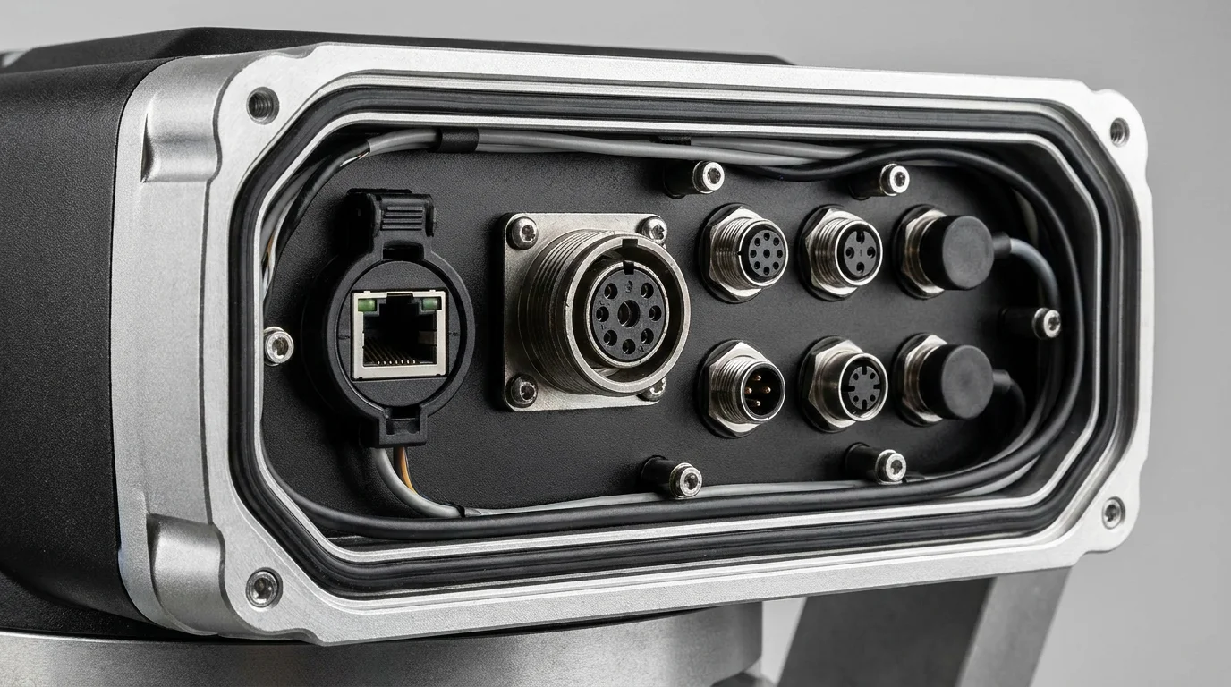
An integrated joint module combines motor, reducer, encoder, and drive electronics into one compact unit.
An integrated joint module combines motor, reducer, encoder, and drive electronics into one compact unit.
A robot joint module — also called a robotic joint actuator or servo joint module — is a complete, ready-to-use actuator assembly that forms one rotational axis of a multi-axis robot arm. It integrates four key subsystems into one compact, sealed unit:
- Motor: Usually a frameless brushless DC (BLDC) torque motor — chosen for its high torque density and thin axial profile.
- Reducer: Typically a harmonic drive or planetary gear set. This multiplies motor torque and reduces output speed. A harmonic drive provides sub-arc-minute backlash; planetary offers lower cost.
- Encoder system: Dual absolute encoders — one on the motor shaft (input side), one on the output flange. This gives full closed-loop position control without needing a homing sequence at power-up.
- Servo driver: An integrated PCB that handles commutation, current/torque control, velocity control, and position control. Communicates with the main robot controller via EtherCAT, CANopen, or other industrial fieldbuses.
When you buy a modular robotic joint, you receive a sealed, IP65-rated cylinder with two flanges (input and output), a connector for power and communication, and a datasheet with the torque-speed curve and wiring diagram. You mount it, plug it in, configure a few registers, and it runs.
Here's the signal chain from command to motion:
- Command: The main robot controller sends a target position, velocity, or torque command over EtherCAT or CAN bus to the joint module's servo driver.
- Commutation: The driver reads the motor-side encoder to determine rotor angle, then commutates the BLDC motor coils in the correct sequence.
- Torque amplification: The motor spins at high speed (~3,000–6,000 RPM) but low torque (~0.1–0.5 Nm). The harmonic drive reducer (ratio 50:1 to 160:1) converts this to low speed (~20–60 RPM) and high torque (6–150 Nm).
- Feedback: The output-side encoder continuously reports the actual joint angle back to the driver. The driver compares commanded vs actual and adjusts motor current in real time — this is the servo control loop, running at 8–16 kHz.
- Output: The output flange rotates to the commanded position with sub-arc-minute accuracy, holding torque against external loads.
All of this happens inside one integrated robot joint module. No external servo drives, no encoder alignment jigs, no separate cabling between components.
A harmonic drive is a precision gear reducer that uses elastic deformation — not conventional gear teeth meshing — to achieve zero-backlash torque transmission. It was invented in the 1950s for aerospace applications and has become the de facto standard in robotics due to its unique combination of high ratio, high torque density, and sub-arc-minute precision.
How it works: Three components — a wave generator (elliptical bearing on the motor shaft), a flexspline (thin-walled flexible steel cup with external teeth), and a circular spline (rigid internal ring gear). As the wave generator rotates, it deforms the flexspline into an ellipse, engaging teeth at two points with the circular spline. Because the flexspline has 2 fewer teeth, one full rotation of the wave generator advances the output by exactly 2 teeth — yielding ratios from 50:1 to 160:1 in a single stage.
Why it matters for robots: No backlash means no positional dead zone. When your cobot arm commands a 0.1mm move, the actuator delivers exactly that — every cycle, for thousands of hours. This is why 85%+ of collaborative robots use harmonic drive robot arm joint modules for their primary axes.
Until about 2018, most industrial robot manufacturers built their own joints from separate components: buy a harmonic drive reducer, source a frameless motor, align them in a custom-machined housing, mount encoders, and wire everything to an external servo drive. This approach has four major problems that integrated robot joint modules solve:
| DIY Approach | Integrated Joint Module |
|---|---|
| 4+ suppliers to manage (reducer, motor, encoder, driver) | 1 supplier, 1 warranty, 1 support contact |
| 2–4 weeks of motor-reducer alignment and encoder calibration per design iteration | Factory-calibrated. Mount and run in hours. |
| Custom housing design, thermal analysis, sealing | IP65 sealed housing included. No mechanical design needed. |
| 18–24 week development cycle for a 6-axis cobot joint system | 1–3 week integration cycle. CAD models provided. |
| $65,000+ in engineering labor for a first prototype | $8,000–12,000 in module cost for a 6-axis arm |
The ROI is clear: unless you're building 500+ robots per year, why use integrated joint modules comes down to saving 4–6 months of development time and $50,000+ in engineering costs — per robot design.
This is one of the most common questions from engineers transitioning from traditional automation to robotics:
| Feature | Servo Motor + Gearbox | Integrated Robot Joint Module |
|---|---|---|
| Integration | Motor, gearbox, encoder, and drive are separate components | All four integrated into one sealed unit |
| Backlash | 3–8 arc-min with precision planetary gearbox | <1 arc-min with harmonic drive |
| Form factor | Long axial length; difficult to package in a robot arm | Compact, pancake-style; designed for joint articulation |
| Hollow shaft | Usually not available | Standard on most models; cables pass through the center |
| Encoder | Single encoder on motor shaft | Dual absolute encoders (motor + output) |
| IP rating | Varies; often IP54 | IP65 standard; IP67 available |
| Best for | Conveyor axes, linear stages, rotary indexers | Robot arm joints, cobot axes, exoskeleton articulation |
In short: a servo motor + gearbox is a general-purpose motion component. A servo joint module is purpose-built for robotic articulation — optimized for the unique combination of compactness, hollow-shaft cabling, dual-loop control, and multi-axis synchronization that robot arms demand.
Torque requirements vary dramatically by joint position and application. Here are the rough industry ranges:
| Robot Type | J1–J2 (Base/Shoulder) | J3–J4 (Elbow) | J5–J6 (Wrist) |
|---|---|---|---|
| Desktop cobot (3kg payload) | 15–30 Nm | 6–15 Nm | 3–6 Nm |
| Standard cobot (5–10kg payload) | 55–90 Nm | 15–30 Nm | 6–15 Nm |
| Industrial arm (10–20kg payload) | 90–150 Nm | 30–55 Nm | 15–30 Nm |
| Humanoid robot (leg joint) | 55–90 Nm | 30–55 Nm | 6–15 Nm |
| Exoskeleton (knee/hip) | 15–55 Nm | N/A | N/A |
Rule of thumb: Always add 20–30% torque headroom above your calculated peak. Dynamic loads during acceleration and deceleration can spike 2–3× above static torque. PlaPivot's robot joint torque range covers 6Nm to 150Nm across six models, covering the full spectrum from desktop cobots to heavy industrial arms.
Getting Started with Robot Joint Modules
If you're new to modular robotic joints, the best next step is to request datasheets and CAD models for the torque range that matches your application. Mounting dimensions, weight, and communication protocols are the three parameters that affect your mechanical and electrical design the most — and you need those numbers on day one of a new robot project.
At PlaPivot, we ship evaluation units worldwide with full dyno test reports, calibration certificates, and STEP files included. Whether you're building your first cobot prototype or scaling to production, the joint modules are the last thing you should have to worry about.
New to Robot Joint Modules? Start Here.
Tell us about your project. We'll recommend the right modules, send datasheets and CAD files, and answer your technical questions within 24 hours.
Request Datasheets & CAD Models