Why This Guide Exists
When comparing robot joint modules, you'll encounter datasheets full of specifications — some critical, some marketing fluff. This guide teaches you to read between the lines. We cover the seven parameters that actually predict how a robotic actuator module will perform in your application, and the test conditions that suppliers sometimes hide.
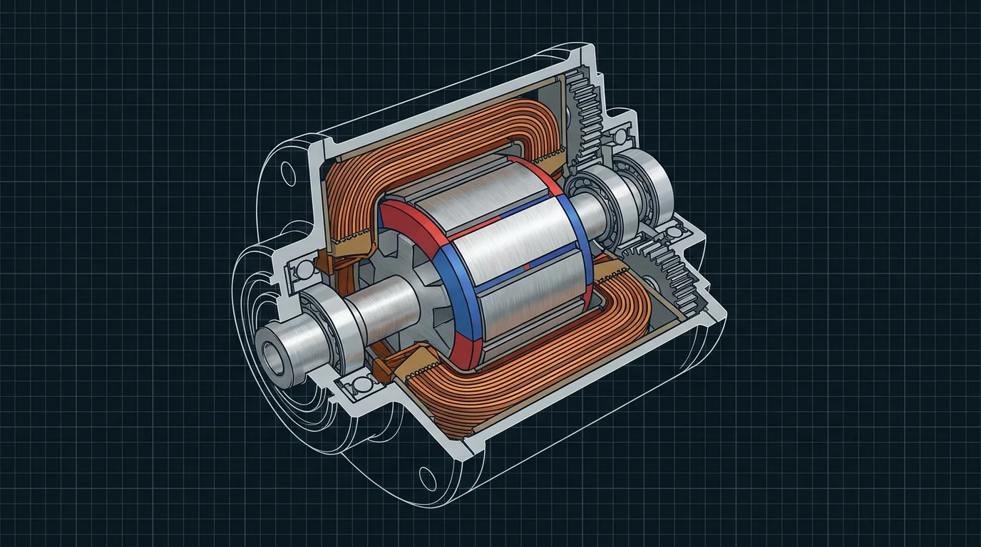
Factory-tested modules ship with verified current and position feedback waveforms — ensuring plug-and-play reliability.
1. Torque: The King Parameter
Every robot joint torque range specification starts with three numbers — but they're not created equal. Here's how to decode them:
| Torque Rating | What It Means | When It Matters |
|---|---|---|
| Rated / Continuous Torque (T_N) | Torque the joint can sustain indefinitely without exceeding thermal limits. Validated at 25°C ambient with natural convection. | This is the number you design around. If your application's steady-state load exceeds T_N, the motor will thermally throttle within minutes. |
| Peak / Maximum Torque (T_max) | Torque available for 1–3 seconds. Limited by motor winding saturation and driver peak current capability. | Acceleration and deceleration phases. If T_max is only 1.2× T_N, the module won't handle dynamic loads well. |
| Stall Torque | Torque at zero speed. Critical for holding position against external loads without backdriving the reducer. | Exoskeleton joints holding a patient's limb. Cobot joints holding position during a safety stop. |
Red Flag: Missing Test Conditions
If a datasheet says "30 Nm torque" without specifying whether it's continuous or peak, at what ambient temperature, and for what duration — assume it's peak at 20°C for 1 second. Real continuous torque at 40°C factory ambient is often 30–50% lower than the headline number. Insist on a torque-speed curve with thermal limits plotted.
PlaPivot's standard: Every PP-series module ships with a dyno-validated torque-speed curve showing continuous and peak limits across the full speed range, at 25°C and 40°C ambient, with natural convection. No asterisks, no fine print.
2. Backlash: The Precision Parameter
Backlash in a robot joint module is the angular clearance (lost motion) when reversing direction. It exists because there must be clearance between meshing gear teeth — or, in a harmonic drive, because the wave generator must overcome elastic deformation of the flexspline.
What Different Backlash Values Mean in Practice
| Backlash | Reduction Type | End-Effector Error (at 500mm reach) | Applications |
|---|---|---|---|
| <0.5 arc-min | Precision harmonic drive | <0.07 mm | Surgical robots, semiconductor handling, optical alignment |
| <1 arc-min | Standard harmonic drive | <0.15 mm | Cobots, precision assembly, dispensing, 3D printing |
| 3–5 arc-min | Precision planetary gear | 0.44–0.73 mm | Palletizing, material handling, simple pick-and-place |
| 8+ arc-min | Standard planetary / spur gear | >1.16 mm | Low-precision rotary drives, conveyors |
Key insight: Backlash is the single most honest specification on a joint module datasheet. It can't be faked with favorable test conditions, and it directly predicts real-world performance. If a supplier is vague about their backlash robot joint module specification ("low backlash" without a number) — look elsewhere. Precision is measured in arc-minutes, not adjectives.
3. Torque Density: Power-to-Weight Ratio
Torque density is expressed in Nm/kg — continuous torque divided by module mass. It's the most telling single number for applications where weight matters: humanoid robots, exoskeletons, aerial manipulators, and space robotics.
Torque Density Comparison (Typical Values at 30–50Nm)
| Technology | Torque Density | Notes |
|---|---|---|
| Harmonic Drive (integrated) | 80–100 Nm/kg | Steel flexspline + frameless motor |
| Harmonic Drive (component only) | 60–80 Nm/kg | Reducer alone; need to add motor mass |
| Planetary (integrated) | 40–60 Nm/kg | Multiple planet gears add weight |
| Cycloidal Drive | 50–70 Nm/kg | Higher shock tolerance, more complex |
| Direct Drive (no reducer) | 5–15 Nm/kg | Low torque density; best for high-speed apps |
For a high torque density actuator in a humanoid robot, every 0.1 Nm/kg improvement in the knee joint saves approximately 0.5 kg in total robot weight (due to cascading effects on upstream joints). This is why harmonic drive servo joint modules dominate legged robotics — nothing else approaches their torque density at the 50–150Nm range.
Thermal management is critical. Well-designed modules maintain rated torque without overheating.
4. Joint Module Efficiency: Where Power Goes
Joint module efficiency is the ratio of mechanical output power to electrical input power. For an integrated robot joint module, efficiency losses occur in three places:
- Reducer (largest loss): Harmonic drives typically 70–85% efficient. The 15–30% loss becomes heat inside the flexspline — this is the primary source of joint temperature rise.
- Motor (moderate loss): I²R copper losses in the windings. Typically 85–92% efficient at rated load.
- Driver electronics (smallest loss): MOSFET switching losses and PCB trace resistance. Typically 95–98% efficient.
System efficiency = reducer × motor × driver: For a typical harmonic drive joint module at rated load: 0.78 × 0.88 × 0.96 ≈ 66% overall efficiency. That means a 30Nm continuous joint consuming 180W electrical might deliver only ~120W of mechanical power. The remaining 60W is heat that must be conducted through the housing.
Why efficiency matters beyond power consumption: Lower efficiency means more heat, and heat limits continuous torque. A module rated at 30Nm T_N at 25°C ambient is often derated to 22–25Nm at 40°C. Always request the thermal derating curve.
5. Reducer Ratio: Speed vs Torque Tradeoff
The reducer ratio robot joint specification tells you the mechanical advantage between motor and output. Common ratios for harmonic drive modules:
| Ratio | Typical Application | Motor Speed → Output Speed |
|---|---|---|
| 50:1 | High-speed wrist joints, fast pick-and-place | 3,000 RPM → 60 RPM |
| 80:1 | General-purpose cobot joints (elbow, shoulder) | 3,000 RPM → 37.5 RPM |
| 100:1 | Precision positioning, surgical robots | 3,000 RPM → 30 RPM |
| 120:1 | Heavy payload cobot base joints | 3,000 RPM → 25 RPM |
| 160:1 | Maximum torque, low speed (palletizing base) | 3,000 RPM → 18.75 RPM |
Higher ratio = more torque multiplication but lower output speed. The sweet spot for most cobot applications is 80:1 to 120:1 — balancing speed for collaborative cycle times with torque for payload capacity. PlaPivot modules are factory-configured with optimized ratios per model; custom ratios available for 50+ unit orders.
Dual absolute encoders provide closed-loop control on both motor and output sides for maximum precision.
6. Encoder Feedback: The Position Sensor
Encoder feedback robotic joint systems use dual absolute encoders — one on the motor shaft (fast, low-resolution) and one on the output flange (slow, high-resolution). Together they provide full-state feedback for closed-loop control.
Encoder Resolution by Bit Depth
| Resolution | Counts per Revolution | Theoretical Angular Resolution | Real-World Use |
|---|---|---|---|
| 17-bit | 131,072 | 10 arc-seconds | Basic position control, non-critical axes |
| 19-bit | 524,288 | 2.5 arc-seconds | Standard cobot joints |
| 23-bit | 8,388,608 | 0.15 arc-seconds | Precision cobots, surgical robots |
| 25-bit | 33,554,432 | 0.04 arc-seconds | Semiconductor, optics, metrology |
Why dual encoders matter: A single encoder on the motor shaft can't detect reducer compliance or output-side position drift. With dual encoders, the driver computes twist (angle difference between motor and output) — which directly correlates with transmitted torque. This enables sensorless torque estimation, collision detection, and impedance control without an external torque sensor.
PlaPivot modules use 23-bit absolute encoders on the output side as standard — providing 0.15 arc-second resolution with multi-turn absolute position memory. No homing, no incremental drift, no battery-backed memory required.
7. Servo Control: The Brain Inside
The servo control joint module architecture determines how the joint behaves dynamically. Three nested control loops run on the integrated driver:
- Current loop (innermost, fastest): Runs at 16–32 kHz. Controls motor phase current to produce commanded torque. Bandwidth: 2–4 kHz.
- Velocity loop: Runs at 4–8 kHz. Controls motor speed using encoder feedback derivative. Bandwidth: 200–500 Hz.
- Position loop (outermost, slowest): Runs at 1–2 kHz. Controls output position using output-side encoder. Bandwidth: 50–150 Hz.
For most industrial automation robot joint applications, a 100Hz position loop bandwidth is sufficient — it means the joint can correct a 0.1° position error in approximately 10ms. For quadruped robots and high-speed pick-and-place, 150Hz+ is needed to stabilize the leg or end-effector within a single motion cycle.
8. Datasheet Comparison Checklist
- ☐ Continuous torque (T_N) — with ambient temperature stated
- ☐ Peak torque (T_max) — with duration (seconds) stated
- ☐ Torque-speed curve — with thermal limits clearly shown
- ☐ Backlash — in arc-minutes, with a number, not a claim
- ☐ Torque density — Nm/kg, calculated from actual module mass
- ☐ Efficiency — reducer, motor, and driver efficiency stated separately
- ☐ Reducer ratio and type (harmonic / planetary / cycloidal)
- ☐ Encoder resolution (bits) and type (absolute / incremental / dual)
- ☐ Control bandwidth — position loop bandwidth in Hz
- ☐ Communication protocol (EtherCAT / CANopen / other)
- ☐ Thermal derating curve — T_N at elevated ambient temperatures
- ☐ IP rating and operating temperature range
If a supplier's datasheet is missing 3 or more of these items, ask for the missing data before ordering. A robotic joint accuracy claim without a backlash specification is marketing, not engineering.
Want Complete Datasheets with Torque Curves?
PlaPivot provides full specifications including dyno-validated torque-speed curves, thermal derating data, and STEP CAD models — before you order.
Request Complete Datasheets