As robots move out of cages and into shared workspaces with humans, safety is no longer an afterthought—it's the primary design constraint. For engineers and system integrators, understanding the safety standards that govern robot joint modules is essential for legal compliance, risk mitigation, and worker protection.
ISO 10218: The Foundation of Robot Safety
ISO 10218 is the primary international standard for industrial robots. It is divided into two parts: Part 1 for robot manufacturers and Part 2 for system integrators. For joint module manufacturers, ISO 10218-1 dictates the fundamental design requirements, including the need for at least one emergency stop input and the ability to monitor speed and position. It sets the stage for more detailed functional safety assessments.
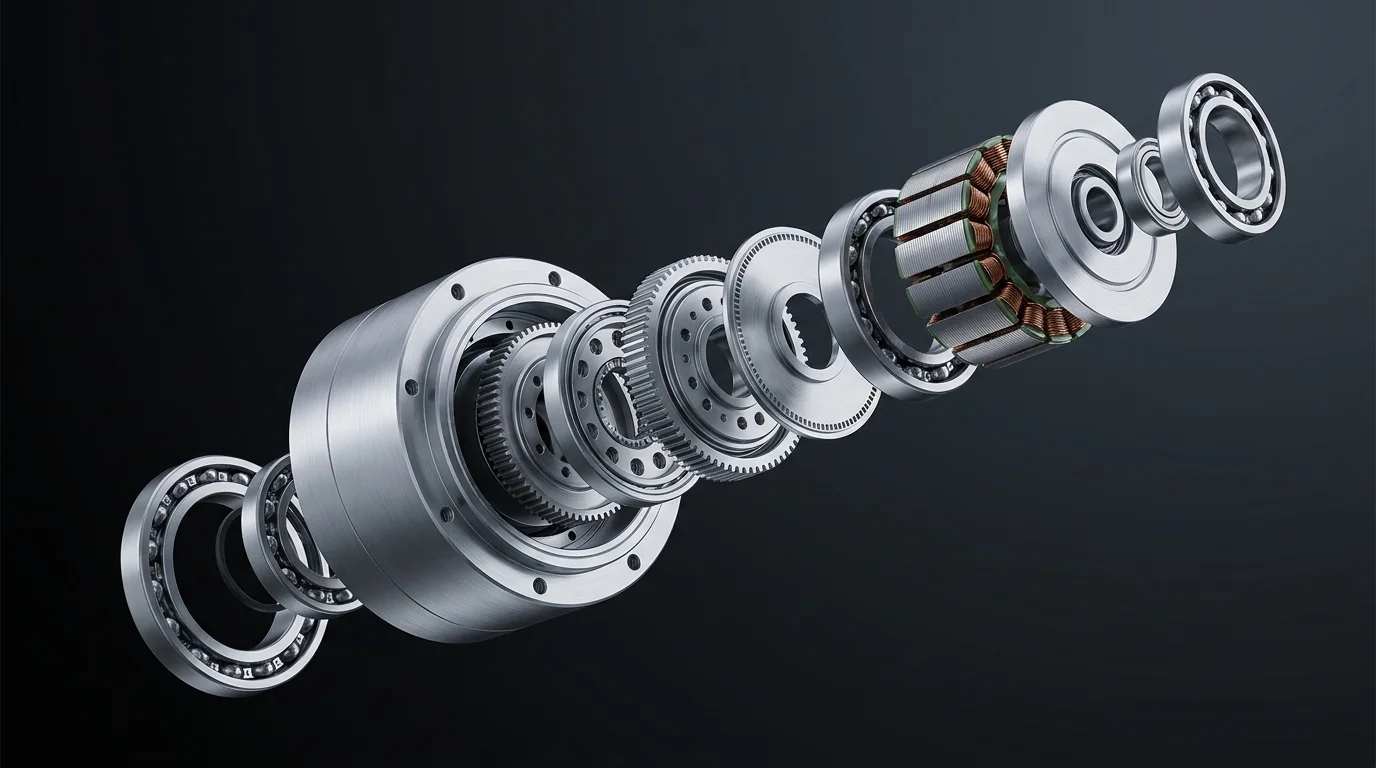
Technical illustration for Safety Standards for Robot Joint Modules: ISO 10218, ISO 13849 and Beyond.
ISO 13849-1: Performance Levels and Reliability
While ISO 10218 tells you *what* to do, ISO 13849-1 tells you *how reliably* you must do it. It introduces the concept of Performance Levels (PL a through e). A joint module intended for a collaborative robot usually needs to meet PL d or PL e. This is achieved through component redundancy (e.g., dual encoders), high Mean Time to Dangerous Failure (MTTFd), and Diagnostic Coverage (DC). When you buy a joint module, you should look for its PL rating in the safety manual.
Functional Safety Features: STO and SBC
Modern integrated actuators include dedicated functional safety hardware. The most common is Safe Torque Off (STO). When triggered, STO removes power from the motor while keeping the controller logic alive. This ensures the motor cannot generate torque and cause movement. Another critical feature is Safe Brake Control (SBC), which ensures the mechanical brake is engaged whenever power is lost or a safety event occurs, preventing the robot arm from collapsing under gravity.
Technical illustration for Safety Standards for Robot Joint Modules: ISO 10218, ISO 13849 and Beyond.
Collaborative Safety and ISO/TS 15066
For collaborative robots (cobots), ISO/TS 15066 provides specific guidance on Power and Force Limiting (PFL). Joint modules for cobots often include torque sensors or advanced current monitoring to detect collisions instantly. The standard defines maximum allowable impact forces for different parts of the human body. Joint modules must be responsive enough to stop the robot within milliseconds of a detected impact to stay within these limits.
Global Compliance and CE Marking
To sell robot modules globally, manufacturers must demonstrate compliance with regional regulations. In the EU, this means meeting the requirements of the Machinery Directive and applying the CE mark. This involves a rigorous process of risk assessment, technical file creation, and often third-party testing by bodies like TÜV or UL. Using pre-certified joint modules significantly simplifies the final certification of the entire robotic system.
Decoding the Ratings: PL, SIL, Category and DC at a Glance
Safety documentation quotes four interlocking numbers, and buyers frequently confuse them. The table below is the quick reference we hand to integrators:
| Term | Standard | What it means | Typical value for a cobot joint |
|---|---|---|---|
| Performance Level (PL) | ISO 13849-1 | Reliability grade of a safety function, a–e | PL d or e |
| SIL | IEC 62061 | Safety integrity level of the same function, 1–3 | SIL 2 |
| Category | ISO 13849-1 | Structural architecture: B, 1, 2, 3, 4 | Cat 3 (redundant, monitored) |
| DC | ISO 13849-1 | Diagnostic coverage — share of dangerous faults detected | 90% (DCavg) for PL d |
| MTTFd | ISO 13849-1 | Mean time to dangerous failure per channel | High (≥30 years) for PL d |
The approximate mapping between the two systems: PL b ≈ SIL 1, PL c ≈ SIL 1, PL d ≈ SIL 2, PL e ≈ SIL 3. A joint's safety functions — STO above all — are typically designed to PL d / SIL 2 or better for collaborative use.
What to Look For in a Joint Module Safety Manual
Before signing off on a module, open its safety manual and verify each item is present — if the vendor cannot produce this documentation, the final CE assessment of your robot will be painful:
- ☐ STO per IEC 61800-5-2, with a stated PL/SIL claim and response time.
- ☐ SBC / brake behavior on power loss and on safety stop — does the arm hold position under gravity?
- ☐ Feedback redundancy: dual absolute encoders and the fault detection that cross-checks them.
- ☐ Temperature and current monitoring that triggers a safe stop on overheat or stall.
- ☐ Certificates: CE (Machinery Directive), declaration of conformity, third-party test reports (TÜV or UL).
- ☐ Wiring guidance for safety inputs — dual-channel, cross-monitored connections to your safety PLC.
Risk Reduction Starts at the Joint: Three Design Choices
Certification is far easier when the joint itself reduces risk instead of relying on external machinery. Three choices carry most of the weight:
- Redundant feedback. 17-bit dual absolute encoders (motor + output) let the controller cross-check position continuously; a mismatch is a detectable fault, not a guess.
- Integrated driver with STO. The safety stop acts inside the joint, removing a whole layer of cabinet-level safety relays and shortening the safety reaction chain.
- 48 V DC power. Compared with 400 V AC servo systems, the lower bus voltage shrinks touch-voltage and arc-energy risk — a real advantage in power-and-force-limiting assessments for shared workspaces.
None of these replaces a system-level risk assessment per ISO 12100 — but each one removes failure modes that the assessment would otherwise have to mitigate.
Ready to start your build?
Our engineering team is ready to help you select the perfect robot joint modules for your application. Get expert advice and a custom quotation within 24 hours.
Get a Quote & DatasheetRelated articles you might find useful: