In 30 Seconds
Real robot projects rarely fail because a motor cannot rotate. They fail when backlash reaches the end effector, continuous torque turns into thermal derating, encoder feedback does not represent output position, communication becomes a weekend-long debugging task, or prototype sourcing blocks the next build. This guide covers seven recurring robot joint module problems and the checks that reduce redesign risk.
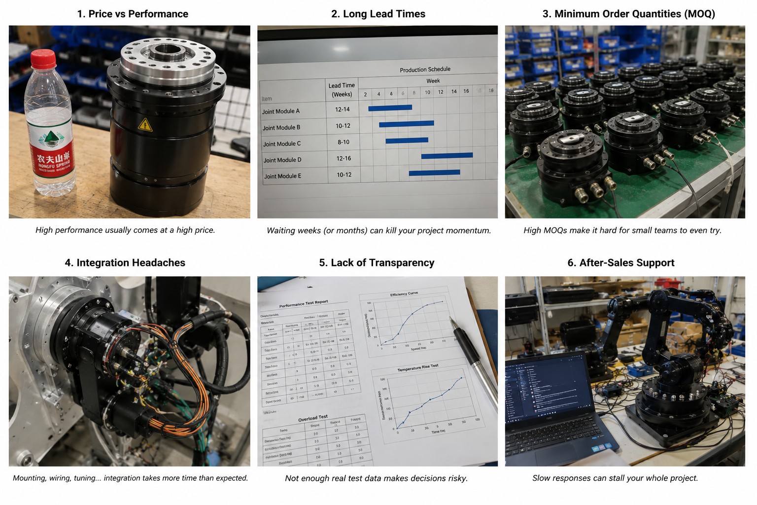
The same integration and sourcing problems appear across research robots, cobots and custom robot arms.
1. Backlash Looks Small on a Datasheet Until It Reaches the End Effector
Backlash is probably the most discussed mechanical problem in custom robot-arm projects. A gearbox may feel reasonably tight when held in your hand, but the problem becomes more obvious after it is installed in a long robot link. A small angular error at the shoulder can become a visible end-effector deviation after it is multiplied through a 500 mm or 800 mm arm segment.
The problem is especially common when using low-cost planetary gearboxes, multi-stage spur gear reductions, 3D-printed gearboxes, poorly preloaded bearings, couplings with torsional play, or reducers whose backlash was not measured under realistic load. For a robot joint module, backlash should never be evaluated as an isolated gearbox specification.
- How is backlash measured, and at what load?
- Is the value measured at the gearbox or at the complete actuator output?
- What happens to backlash under rated torque?
- Is there an output-side encoder?
- What is the repeatability of the complete joint?
Also consider output-bearing stiffness, torsional rigidity, gearbox preload, structural deflection, shaft coupling and load direction. A low-backlash reducer inside a mechanically flexible joint can still produce poor positioning performance.
2. High Torque Is Easy to Advertise and Hard to Deliver Continuously
A robot joint module may advertise 50 Nm, 80 Nm or 100 Nm, but that number means little without the operating condition. Rated continuous torque, short-term peak torque, startup torque, holding torque, emergency-stop torque and impact torque are different values.
Consider a 5 kg payload located 0.6 m from a shoulder axis:
5 × 9.81 × 0.6 ≈ 29.4 Nm
That gravity torque excludes forearm mass, wrist actuator mass, gripper mass, cables, acceleration and safety factor. A 35 Nm actuator may therefore have little practical margin. The problem is particularly serious at shoulder and hip joints, where the actuator must continuously fight gravity while accelerating the payload and downstream links.
Heat changes winding resistance, torque capability, encoder stability, driver performance, lubricant behavior and service life. Compare continuous torque curves, peak-torque duration, thermal derating, winding-temperature protection, driver-temperature monitoring and realistic duty-cycle recommendations. A five-second bench test is not equivalent to an eight-hour production cycle.
3. Motor-Side Position Is Not Always Joint-Side Position
Many servo systems place an encoder on the motor shaft. That is useful for commutation and closed-loop speed control, but it does not always tell you exactly where the robot joint output flange is located. Between the motor and output there may be gearbox compliance, backlash, flexspline deformation, shaft torsion, bearing deformation and assembly tolerance.
Why dual encoders are useful
A motor-side encoder supports high-speed motor control and commutation. An output-side encoder measures the actual joint position after the reducer. This lets the controller see what the gearbox is doing instead of assuming that motor position perfectly represents joint position.
Output-side feedback is particularly useful for cobots, humanoids, force control, precision positioning, teleoperation, medical robotics and inspection systems. It also makes debugging easier: engineers can determine whether an error comes from the motor loop or the mechanical transmission.
4. The Actuator Works Until You Try to Integrate the Communication Protocol
You connect the manufacturer’s USB adapter, open its configuration software and the motor rotates perfectly. Then you try to control it from an STM32, Raspberry Pi, NVIDIA Jetson, industrial PC, PLC or ROS controller. Now you need to understand CAN message IDs, byte order, command modes, encoder scaling, torque units, velocity units, fault registers, node IDs, heartbeat behavior, emergency-stop logic and startup sequence.
“CAN supported” is not enough. Ask whether the actuator uses CANopen, CAN FD, proprietary CAN, MIT-style commands or custom frames. For EtherCAT, request ESI files, object dictionaries, register maps, sample code and troubleshooting documentation. Good actuator documentation can save more engineering time than a small difference in component price.
5. Wiring Becomes a Mechanical Design Problem
A single robot joint is easy to wire. A six-axis robot is not. Each axis may require DC power, communication, encoder signals, brake control, temperature sensing, torque sensing, end-effector power and sensor cables. Those cables must pass through rotating joints without pinching, exceeding their bending radius, creating friction, introducing electromagnetic interference or limiting motion.
This is where hollow-shaft joint modules become valuable. A central bore allows cables to pass through the actuator instead of being routed around the housing, improving cable protection, serviceability, packaging and range of motion. Cable routing should be considered before the mechanical design is finalized—not after six actuators have already been selected.
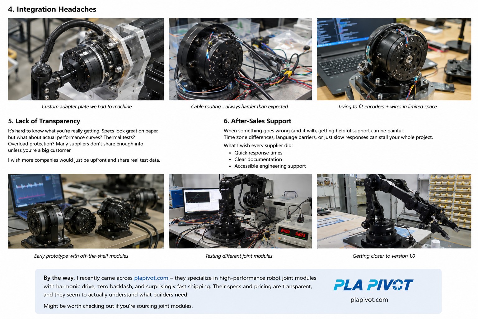
Mounting, wiring, tuning, validation and support can take longer than the first mechanical design.
6. Cheap Components Can Become Expensive Engineering
There is a recurring temptation in prototype robotics: buy the least expensive motor, gearbox, encoder, driver and bearing separately. On paper the bill of materials looks excellent. Then the hidden engineering cost appears.
- Design the motor housing and gearbox interface.
- Select bearings, output flange and encoder alignment.
- Design the driver enclosure and route the wiring.
- Machine, assemble and calibrate the parts.
- Tune the servo and test backlash, thermal performance and repeatability.
If the first version does not work, the process repeats. For a university research project that may be part of the learning process. For a robotics startup trying to ship a manipulator, actuator development can become a distraction. The better question is not “How much does the gearbox cost?” but “How much engineering time does it take to create a reliable joint?”
7. Buying One Prototype Is Often Harder Than Buying 500 Units
Many projects begin with one university robot, two prototype arms, three humanoid joints or five evaluation actuators. At this stage, engineers need flexibility, but many industrial suppliers are optimized for production orders rather than development quantities.
- High MOQ requirements or limited sample availability
- Long lead times and slow technical responses
- Unwillingness to modify firmware or provide CAD files
- Limited support before a volume order
This creates a gap: the customer is not a hobbyist, but is not ready to order 1,000 units either. Small-batch availability reduces development risk by allowing engineers to validate sizing, build one axis, test control and thermal performance, complete a prototype and scale gradually. The ideal supplier supports the transition from prototype to pilot production to volume manufacturing.
What Engineers Actually Need From a Robot Joint Module
Mechanical
- Low backlash and high torsional stiffness
- Rigid output bearing and compact diameter
- Low weight and hollow-shaft cable routing
Electrical
- Integrated servo driver
- Absolute encoder feedback
- Temperature monitoring and brake options
Communication and integration
- CANopen or CAN FD, with EtherCAT for synchronized systems
- STEP files, dimensional drawings and wiring diagrams
- Control examples, torque-speed curves and thermal data
Supply
- Prototype quantities and predictable lead times
- Engineering support and customization options
- Production scalability
Where Integrated Robot Joint Modules Make the Most Sense
Integrated actuators are particularly useful when development speed and packaging density matter. Common applications include collaborative robot arms, humanoids, mobile manipulators, inspection robots, agricultural robots, rehabilitation equipment, medical robotics, laboratory automation and research platforms.
Instead of engineering the motor, harmonic reducer, encoder, servo driver, bearings and housing separately, a development team can treat the entire joint as one motion-control component. This simplifies mechanical design and shortens the path from CAD model to moving prototype.
How PlaPivot Approaches These Problems
PlaPivot develops integrated robot joint modules for robot arms, humanoids, automation equipment and research platforms. Rather than supplying only a motor or reducer, PlaPivot joint modules combine the key components required for a complete robotic axis, including motor, reducer, encoder feedback, integrated driver and communication interface.
The current portfolio includes harmonic rotary, PRO harmonic, planetary rotary and linear joint modules. Depending on the model and configuration, engineers can specify EtherCAT, CAN or CAN FD communication, dual absolute encoders, hollow-shaft routing and brake options. The goal is straightforward: let the robotics team spend more time building the robot—and less time rebuilding the joint.
Final Thoughts
Robot joint design looks simple until you try to build one: motor, gearbox, encoder, driver, bearing and housing. The difficulty is making those components work together with enough precision, stiffness, thermal stability and reliability to survive inside a real robot.
Before selecting a robot joint module, ask:
- How much backlash does the complete joint have?
- What torque can it continuously deliver?
- Where is position actually measured?
- How difficult is communication integration?
- How will cables pass through the joint?
- What technical documentation is available?
- Can I buy samples before committing to production?
Choosing the right joint architecture early can save weeks—or months—of redesign.
Need Help Sizing a Robot Joint?
Send us your required torque, speed, joint dimensions, payload, link length, communication protocol and expected quantity. Our engineering team can help identify a suitable configuration for prototype testing and production.
Request Quote & Datasheet